Fequently Asked Questions
Also, see our Quick Reference Guide for information concerning
RS485, RS422, RS232, and RS423: Quick Reference Guide
RS485 (2-wire, half-duplex, differential, multi-drop (32 nodes), communications
standard for distances up to 4000ft.)
The RS485 standard addresses the problem of data transmission, where a balanced
(differential) transmission line is used in a multi-drop (party line) configuration
(or point-to-point if only two devices are on the network). Up to 32-nodes
(drivers and receivers) are allowed on one multi-drop, bi-directional network.
Data rates of up to 10M bps are supported over short distances (40ft.). At
the four-thousand foot distance limit, data rates of up to 100K bps are allowable.
RS485 specifies a 2-wire, half-duplex communications bus. Because there are
differences between RS485 and RS422(minor in many instances, except for loading
[12K vs. 4K) many people refere to 4-wire RS485. While RS485 is a 2-wire standard,
it does offer 32 nodes on a network, on the other hand RS422 (a 4-wire standard)
only specifies up to 10 nodes. Therefore, while not technically correct, it
does make some sence to refer to a 4-wire RS485 network that would extend
the number of nodes on a 4-wire network to 32 standard loads.
The RS485 standard only specifies electrical characteristics of the driver
and the receiver, it does not specify or recommend any protocol. Because matters
of protocol are left to the user, it is often difficult (if not impossible)
to connect RS485 devices from different manufacturers on the same network.
The RS485 standard allows the user to configure inexpensive local networks
and multidrop communications links using twisted pair wire. A typical RS485
network can operate properly in the presence of reasonable ground differential
voltages, withstand driver contentious situations, provide reliable communications
in electrically noisy environments (good common mode rejection using twisted
pair cable, shielding provides additional protection), and support thirty-two
or more (many IC manufacturers have 1/2, 1/4, 1/8 unit load devices) drivers
and receivers on the line.
Twisted pair wire with a characteristic impedance of 120 ohms is recommended
with 120 ohm termination at each end of the communications line. The common-mode
voltage range is -7V to +12V. A driver in the high impedence (off) state is
able to remain in this state over the common mode range, whether power is
applied or not. The receiver is able to respond to differential signal levels
of 200mV over the common mode range. The receiver load impedence is 12K ohms
(or higher) and transmitter "leakage" current is ±100µA (or less)
in either the powered or unpowered state. Unloaded driver output differential
voltage can be as high as ±6V. Loaded driver voltage (32 nodes on the
network and termination) should typically exceed ±1.5V.
FAQ Index
RS422 (4-wire, full-duplex, differential, multi-drop (10 nodes), communications
standard)
While RS422 is comparable to RS485, it is limited to unidirectional data
traffic, and is terminated only on the end of the line opposite the transmitter.
One transmitter and 10 receivers are allowed on a network, with a distance
limit of 3600ft. RS422 was on the market prior to RS485; however, due to loading
limitations, one of the best uses of RS422 is probably in point-to-point communications,
such as RS232 extension cords. By converting from single-ended RS232 to differential
RS422 and then, converting back from RS422 to RS232 at the other end of the
line, distance and noise immunity can be greatly improved.
FAQ Index
RS232 (3-wire, full-duplex, single-ended, 50ft cable limit)
RS232 was developed in the 1960s, and among other things, specified an electrical
standard, a protocol standard, handshaking, and connector pin-out. In general,
many current applications for RS232 use only the electrical standard (3-wires,
TDX, RXD, Common) and connector pin-out. While handshaking is still with us,
it is usually best to disable it in software (if possible) and/or "loop-back"
the pairs of signals (RTS to CTS, DTR to DSR, etc.) While RS232 was rumored to be on the "way out" with the advent of many of the new communications
standards, it is still alive and well today. While the standard only supports
low data rates and short line length (50ft.) it is still widely used and,
very useful in many applications. With an external converters (RS232 to RS485)
many of the limitations of RS232 can be improved, to take advantage of, the
superior properties of differential communications (2-wire or 4-wire).
FAQ Index
Converters (RS232 to RS485, RS232 to RS422, RS485 to RS422)
Converters in general can be used to change the electrical characteristice
of one communications standard into another, to take advantage of the best
properties of the alternate standard selected. For example, an Automatic RS232 to RS485
converter, could be connected to a computer's RS232, full-duplex port, and
transform it into an RS485 half-duplex, multi-drop network at distances up
to 4000ft. Converters in most instances, pass data through the interface without
changing the timing and/or protocol. While the conversion is "transparent"
the software must be able to communicate with the expanded network features.
An "Automatic Converter" (RS232 to RS485) will turn on the
RS485 transmitter when data is detected on the RS232 port, and revert back
into the receive mode after a character has been sent. This avoids timing
problems (and software changes) that are difficult to deal with in typical
systems. When full-duplex is converted into half-duplex only one device at
a time can transmit data. Automatic Converters take care of the timing problems
and allow fast communications without software intervention.
FAQ Index
Termination for RS485/RS422 Networks
Additional information coming soon!
FAQ Index
Bias (failsafe) for RS485/RS422 Networks
When there is no data activity on an RS485 network (or in many instances RS422
networks, other than point-to-point), the communications lines are "floating"
and, thus susceptible to external noise or interference. Receivers on a network
(RS485 or RS422) have built in hysteresis (200mV differential required to
insure known state). To insure that a receiver stays in an inactive state,
when no data signal is present, bias is generally added to a network at one
or more locations.
FAQ Index
Repeaters
Additional information coming soon!
FAQ Index
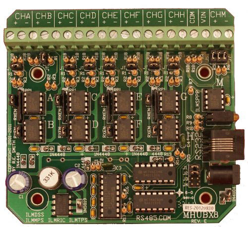
Multiport Repeaters
Once an RS485 network exceeds about 32 nodes on a network, serious consideration
should be given to using galvanic isolation. Even though some IC manufacturers
offer light loading devices, that can accommodate 256 or even 400 nodes on
one RS485 network, you may NOT want to build such a network for a few reasons.
One reason is that, large networks accumulate distributed electrical noise
which can make communications unreliable. In general it is very important
not to run communications wires in the same trough or conduit or in parallel
with AC power cables. Maintain as much distance as possible and cross any
power cable at a right angle. While shielding is not specified for RS485 systems,
it can help in many instances. By "isolating" sections of a large
network, the accumulated noise on one isolated leg is not so likely to cause
a data error that will propagate to another leg of the network. Galvanic isolation
will break a large problem into several small, but manageable ones. Galvanic
isolation can also help eliminate "ground loops."
Another potential problem with large networks without isolation, is that severe
damage can occur to your entire system, if a high voltage source is connected
(accidentally or otherwise) to your communications lines. Your entire network
could be damaged. With galvanic isolation the damage is generally limited
to only one leg of the network, except in extreme cases of very high voltage
(induced by lightening for example). While it goes against conventional wisdom,
and can potentially cause a problem with circulating currents by grounding
a shielded cable at both ends, this method is very effective at keeping induced
lightening noise away from the communications lines. In the alternative, ground
one end of the shield and connect the other end to ground through a bi-directional
transient protector (from a few volts to a few hundred volts depending on
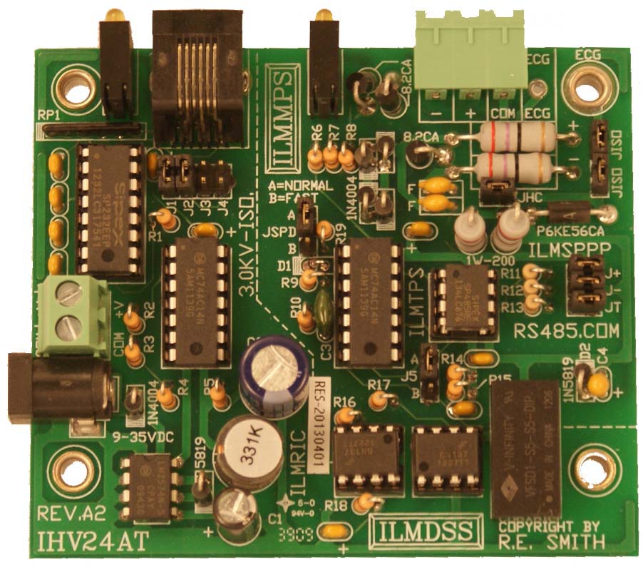
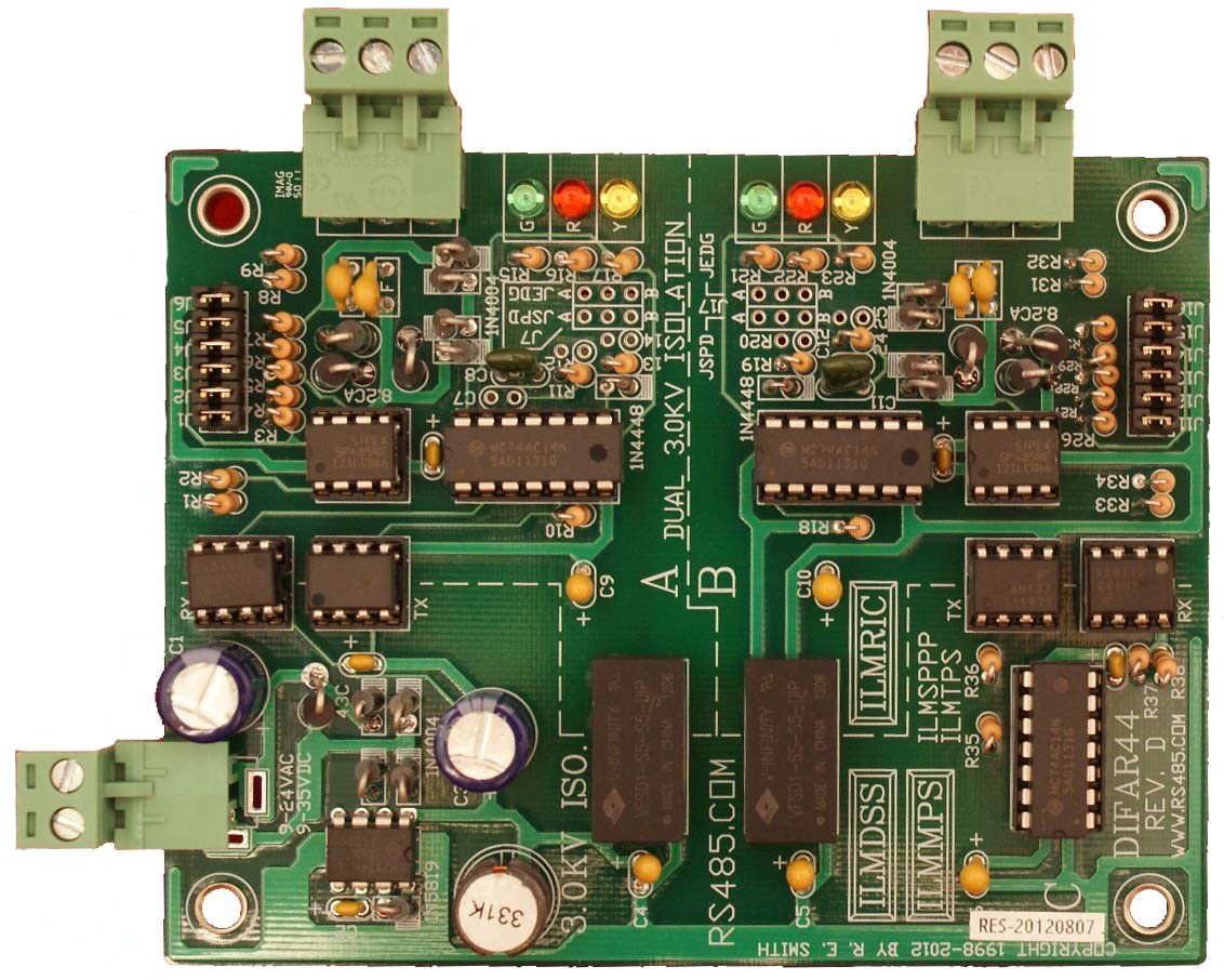
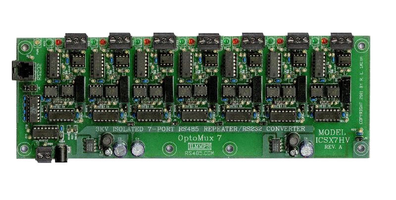
the situation). R.E.Smith also provides an extensive line of optical/transformer
isolated repeaters and multi-port repeaters as well as a series of fiber optic
products which provide very high isolation. These products are extremely effective
in applications involving industrial control, large RS485 networks, outdoor
data links between buildings, etc.
In general RS485 is designed for multi-drop, "daisy-chain" operation
over a single twisted pair cable with a nominal characteristic impedance of
120 Ohms. This cable is usually 24AWG. Category-5 cable will generally work
well in most instances even though its characteristic impedance is 100 Ohms.
"Tap points" or "T" connections should be short to eliminate
reflections. It is possible to connect several RS485 circuits in parallel
if the distances are below about 200 feet per leg @ 9600bps. At greater distances
and higher data rates, the cable impedances add up and load the network. In
addition there is no good way to add terminations resistors at the ends of
a "star" network. The combination of the cable impedances and/or
termination resistors will load the network and can make communications unreliable.
FAQ Index
Galvanic Isolation
Once an RS485 network exceeds about 32 nodes on a network, serious consideration
should be given to using galvanic isolation. Even though some IC manufacturers
offer light loading devices, that can accommodate 256 or even 400 nodes on
one RS485 network, you may NOT want to build such a network for a few reasons.
One reason is that, large networks accumulate distributed electrical noise
which can make communications unreliable. In general it is very important
not to run communications wires in the same trough or conduit or in parallel
with AC power cables. Maintain as much distance as possible and cross any
power cable at a right angle. While shielding is not specified for RS485 systems,
it can help in many instances. By "isolating" sections of a large
network, the accumulated noise on one isolated leg is not so likely to cause
a data error that will propagate to another leg of the network. Galvanic isolation
will break a large problem into several small, but manageable ones. Galvanic
isolation can also help eliminate "ground loops."
Another potential problem with large networks without isolation, is that severe
damage can occur to your entire system, if a high voltage source is connected
(accidentally or otherwise) to your communications lines. Your entire network
could be damaged. With galvanic isolation the damage is generally limited
to only one leg of the network, except in extreme cases of very high voltage
(induced by lightening for example). While it goes against conventional wisdom,
and can potentially cause a problem with circulating currents by grounding
a shielded cable at both ends, this method is very effective at keeping induced
lightening noise away from the communications lines. In the alternative, ground
one end of the shield and connect the other end to ground through a bi-directional
transient protector (from a few volts to a few hundred volts depending on
the situation). R.E.Smith also provides an extensive line of optical/transformer
isolated repeaters and multi-port repeaters as well as a series of fiber optic
products which provide very high isolation. These products are extremely effective
in applications involving industrial control, large RS485 networks, outdoor
data links between buildings, etc.
In general RS485 is designed for multi-drop, "daisy-chain" operation
over a single twisted pair cable with a nominal characteristic impedance of
120 Ohms. This cable is usually 24AWG. Category-5 cable will generally work
well in most instances even though its characteristic impedance is 100 Ohms.
"Tap points" or "T" connections should be short to eliminate
reflections. It is possible to connect several RS485 circuits in parallel
if the distances are below about 200 feet per leg @ 9600bps. At greater distances
and higher data rates, the cable impedances add up and load the network. In
addition there is no good way to add terminations resistors at the ends of
a "star" network. The combination of the cable impedances and/or
termination resistors will load the network and can make communications unreliable.
FAQ Index
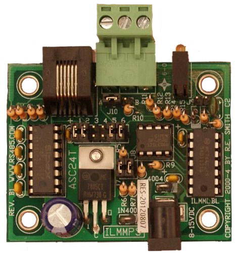
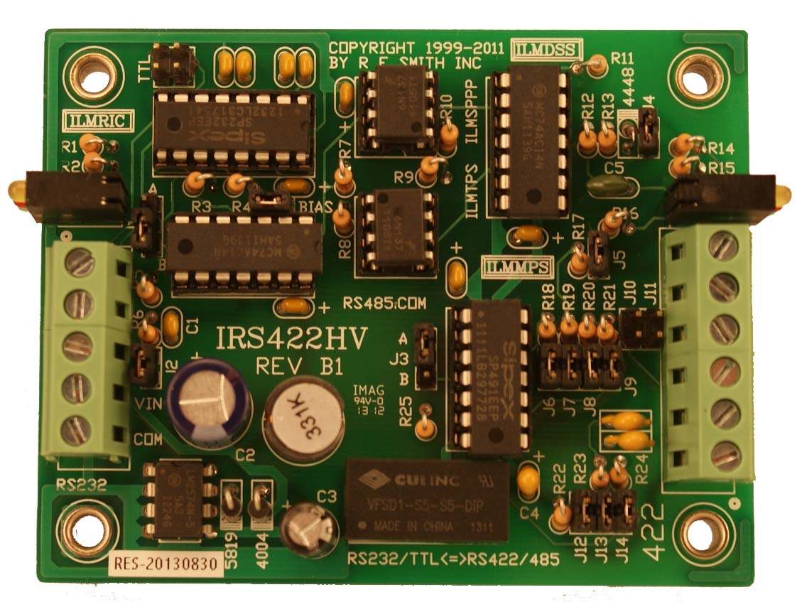
Popular Products:
"Let me spin a very large
RS485 network for you!"
 |